I²C Transceiver
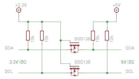
 Following schematics is an I²C bidirectional voltage level transceiver made with only two Mosfet transistors.
How this works
The following three states should be considered during the operation of the level shifter:
-
No device is pulling down the bus line. The bus line of the ‘lower-voltage’ section is pulled up by its pull-up resistors Rp to 3.3 V. The gate and the source of the MOS-FET are both at 3.3 V, so its VGS is below the threshold voltage and the MOS-FET is not conducting. This allows the bus line at the ‘higher-voltage’ section to be pulled up by its pull-up resistor R to 5 V. So the bus lines of both sections are HIGH, but at a different voltage level.
-
A 3.3 V device pulls down the bus line to a LOW level. The source of the MOS-FET also becomes LOW, while the gate stays at 3.3 V. VGS rises above the threshold and the MOS-FET starts to conduct. The bus line of the ‘higher-voltage’ section is then also pulled down to a LOW level by the 3.3 V device via the conducting MOS-FET. So the bus lines of both sections go LOW to the same voltage level.
-
A 5 V device pulls down the bus line to a LOW level. The drain-substrate diode of the MOS-FET the ‘lower-voltage’ section is pulled down until VGS passes the threshold and the MOS-FET starts to conduct. The bus line of the ‘lower-voltage’ section is then further pulled down to a LOW level by the 5 V device via the conducting MOS-FET. So the bus lines of both sections go LOW to the same voltage level.
One constraint, Right side voltage (5V) must be higher or equal to left side voltage (3.3V)