Ethernet schematics
Reading time : 3 minutes
Published on 17 Jun 2020 - Updated on 05 Dec 2020
Schematics
- Check Power pins have the right voltage
- Check for internal power regulators configuration
- Check ethernet PHY I/O voltage levels
- Check crystal frequency, capacitive and resistive load
- Check if reset signal is correctly wired
- Check that PHY is reset at cold and warm boot
- Check RGMII signals are right connected
- Check that MDI signals are right connected
- Check Symbols
- 1x100 nF capacitor per power pin
- Check that terminations are correct
- Check for external required pull up / pull down
- Check that Leds are correctly wired
- Check that interrupts is connected to CPU
- Check that Thermal pad is correctly wired
- Check calibration resistor values
- Check to place an optional ESD device on MDI pins
- Check MDI signals polarity
- Check Serdes signal polarity
- Check how to handle NC pins
- If there is a need for a ferrite bead, make sure there is a bypass capacitor before and after it
- Check that PHYs have different PHY address
- Display configuration table on schematics
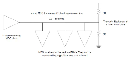
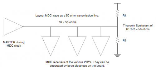
- MDC signal shall have a termination resistor near each receiver

- MDIO needs a pull up resistor between 1.5k and 10k
- Oscillators tolerance is +/-50ppm, output jitter is <200ps
Copper
- If PHY does not integrate termination, add 100 Ohms termination resistors to MDI+/-
- Check for unused MDI pins
- Maximum length for MDI pins is 5 inches
- Check for center tap voltage requirement.
- Center tap decoupling capacitor is 100nF
- Check magnetics pinout
RGMII
- TX pins are connected to RX pins
- Unused RX output pins should be left NC
- Unused TX input pins should be pulled low
- If there is no internal impedance calibration, add termination to RXD and RX_CLK pins
SGMII
- 10 nF serial capacitors
- Check polarities
Schematics Checklist
| Document | Category | Item |
|---|---|---|
| Schematics | LAN | Check that ethernet signals are connected to hardware capable pins |
| Schematics | LAN | Check signal voltage level |
| Schematics | LAN | Connector LED are correctly wired |
| Schematics | LAN | Connector LED check colors |
| Schematics | LAN | LAN1 uses first CPU controller |
| Schematics | LAN | Wake on LAN interrupt does not power up the board by default |
| 3D Files | LAN | Check that latch is easy to disconnect |
| Schematics | LAN - RGMII | check if there is a need of delay function |
| Schematics | LAN - RGMII | TX pins are connected to RX pins |
| Schematics | LAN - RGMII | Unused RX output pins should be left NC |
| Schematics | LAN - RGMII | Unused TX input pins should be pulled low |
| Schematics | LAN - RGMII | If there is no internal impedance calibration, add termination to RXD and RX_CLK pins |
| Schematics | LAN - SGMII | Check that there is a 10nF serial capacitor on TX and RX signals |
| Schematics | LAN - SGMII | Check that SGMII signals are connected to SGMII hardware capable Serdes port |
| Schematics | LAN - MDIO | MDI signals are right connected |
| Schematics | LAN - MDIO | LAN1 has 0 address on MDIO bus, LAN2 has 1 address |
| Schematics | LAN - MDIO | There is a thevenin termination at each end of bus |
| Schematics | LAN - MDIO | Check that GE_MDIO has a 2kOhm pullup resistor |
| Schematics | LAN - MDIO | There is an optional ESD device on MDI pins |
| Schematics | LAN - MDIO | LAN1 has Address 0, LAN2 had Address 1 |
| Schematics | LAN - Connector | If PHY does not integrate termination, add 100 Ohms termination resistors to MDI+/- |
| Schematics | LAN - Connector | MDI signals polarity is correct |
| Schematics | LAN - Connector | Check for center tap voltage requirement |
| Schematics | LAN - Connector | Center tap decoupling capacitor is 100nF |