CPU Layout
Reading time : 2 minutes
Published on 28 Apr 2020 - Updated on 05 Dec 2020
Power supply
- Capacitors via are routed as follow

- Bulk capacitors : 22uF every square inch per power plane
- Decoupling capacitors : 1x100nF per power ball
- CPU core low voltages power planes are as large as possible
- CPU analog power planes are as large as possible
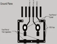
Clock
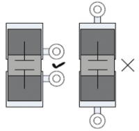
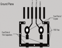
- Crystal are as close as possible to the device
- Crystal trace width is 12 mils
- There is a ground ring around crystals

DRAM
- Check length of all signals
- Clock are routed as differential pairs
- DQS signals are routed as differential pairs
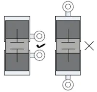
- There is no reference plane change on the same layer
- When there is a reference plane change, add bypass capacitors
PCI Express
- Signals are routed as differential pairs
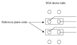
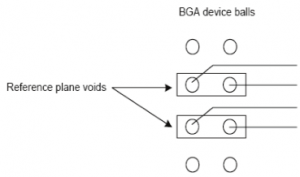
- If signal escape from BGA without a VIA, add a plane void under

- Connector : Place serial capacitors close to the connector on transmitter side
- Onboard : Place serial capacitor near receiver device pin
- Check clock termination resistor placement
- Check calibration resistor placement
- Add plane void under SMT PCIe connector
- Check that there is no reference plane change
- Add plane void under serial capacitors
RGMII
- Check that maximum signal length is less than 6 inches
- Check if there is a need for an external delay
- Maximum skew for any signal group is +/- 0.1 inch (TX or RX)
- Check that there is no reference plane change
- When there is a reference plane change, add bypass capacitors
SGMII
- SGMII signals are routed as differential pairs
- If signal escape from BGA without a VIA, add a plane void under
- Add reference plane void under serial capacitors
- Maximum length is 16 inch
- Check calibration resistor placement
- Check that there is no reference plane change
SATA
- SATA signals are routed as differential pairs
- If signal escape from BGA without a VIA, add a plane void under
- Add reference plane void under serial capacitors
- Maximum length is 4 inch
- Check calibration resistor placement
- Add plane void under SMT SATA connector
- Check that there is no reference plane change
USB
- USB signals are routed as differential pairs
- If signal escape from BGA without a VIA, add a plane void unde
- Maximum length is 5 inch
- Maximum skew is 150 mils
- Check calibration resistor placement
- Check that EMI/ESD protection is close to connector (max 0.6 inch)
- Check that VBUS capacitor is close to the connector
- Check that there is no reference plane change