Fixing an Airelec Indigo towel dryer

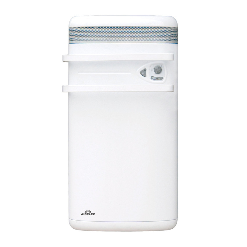
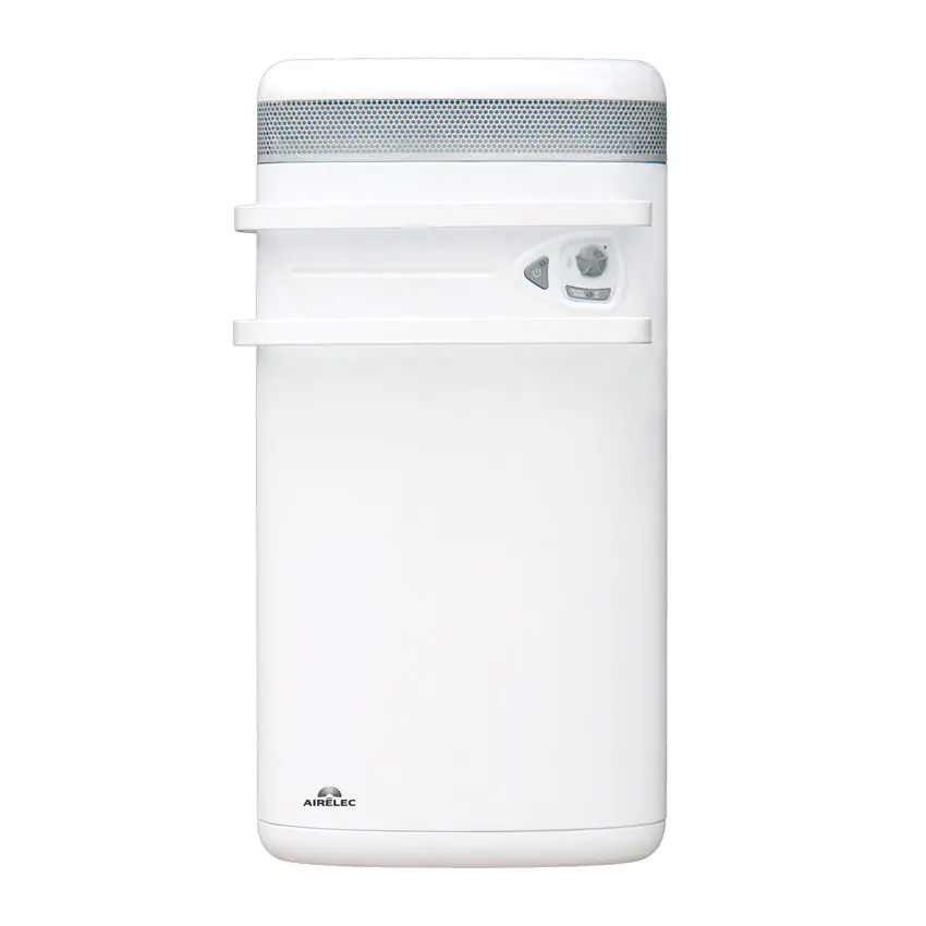
A fresh article with something new to troubleshoot. This time I will repair a tower rail that belongs to my father. It is an Airelec Indigo model, also sold under the Noirot brand.
This heater has two functions. A heating mode with a single heating element and a “forced operation” mode that allows you to quickly heat the bathroom before taking a shower. In the last mode, the heater enables a second heating element coupled with a fan.
This device works perfectly in simple heating mode, but when I enable the “forced operation” mode, the fan starts for a brief amount of time, then turns off, then turns on again for two seconds and so on. After several minutes of on-off cycles, the fan works continuously. At first glance, it looks like a power supply or a chip reset issue.
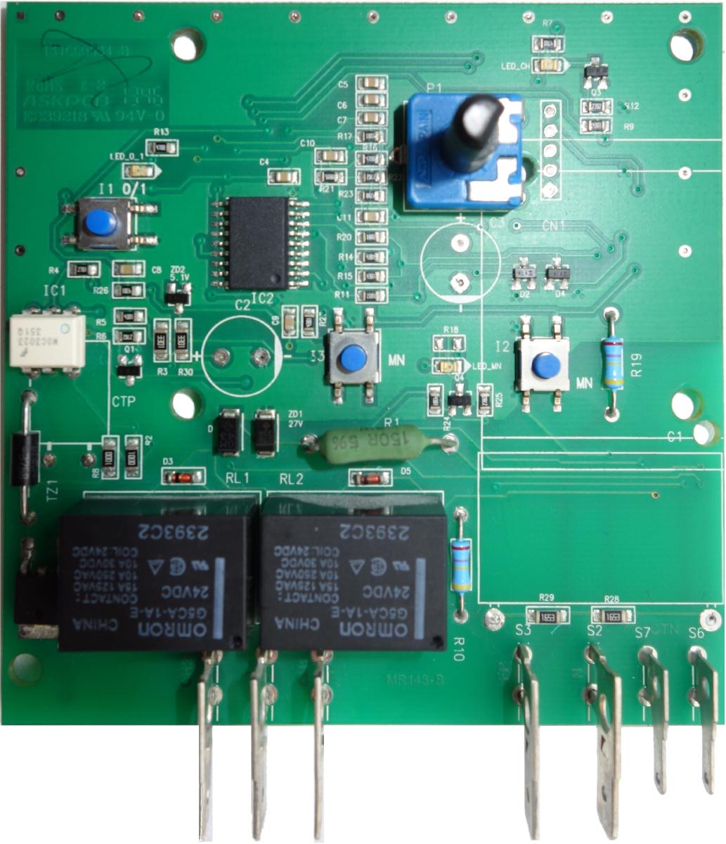
During device disassembly, I realized that it is a good quality heater, it is strong and robust! There are no electronics except a controller PCB. I will focus on how I managed to repair the controller board (yes … spoiler… I repaired it! : grin: )
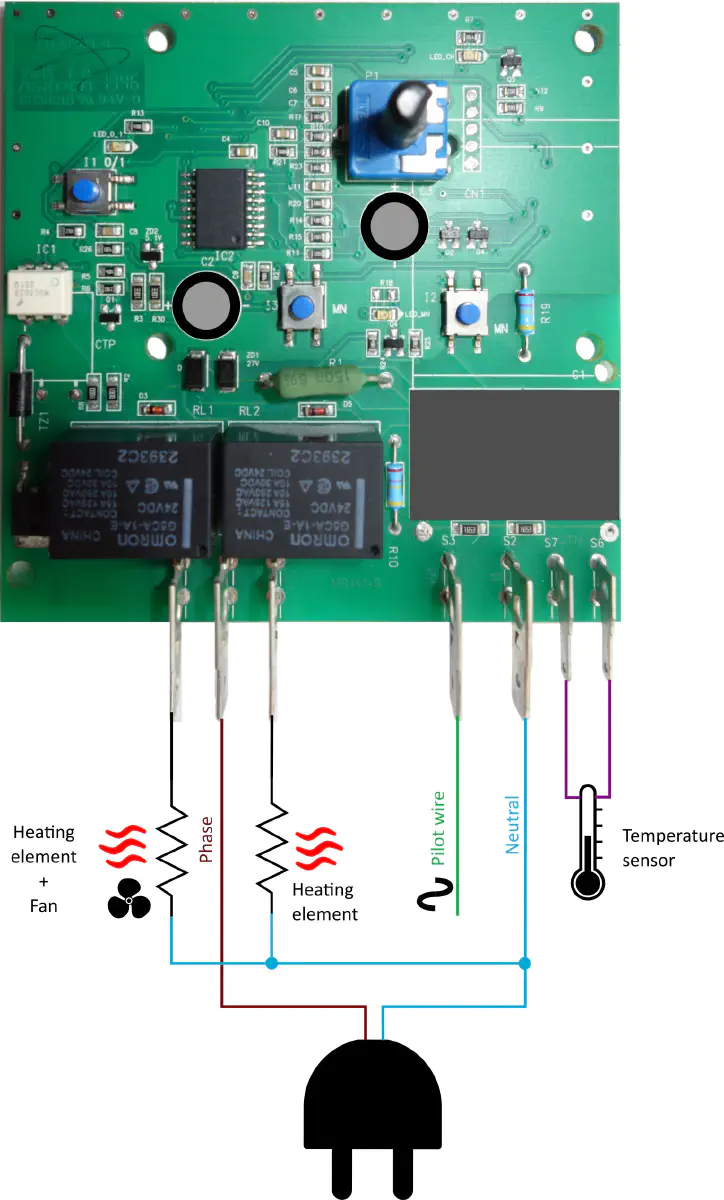
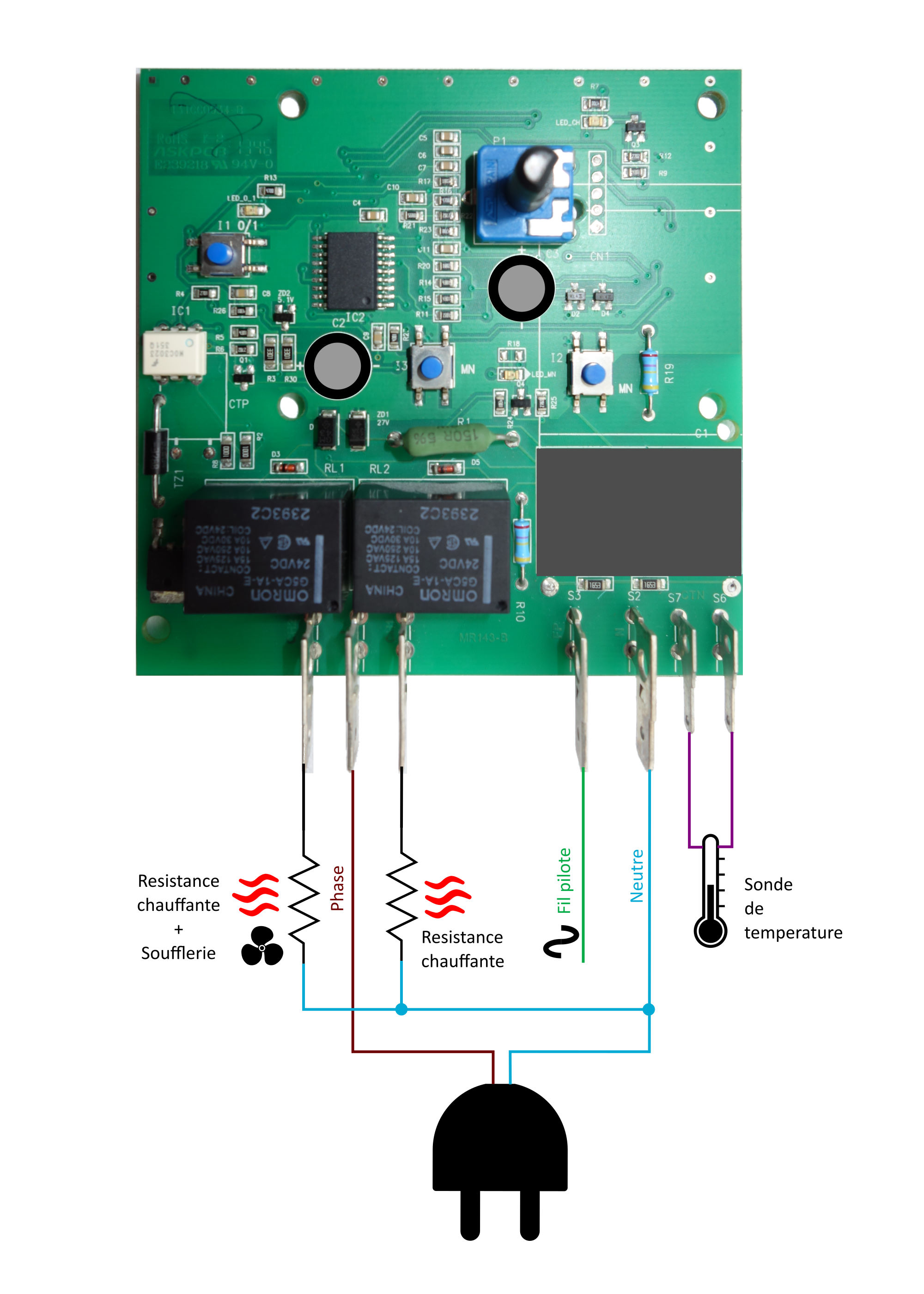
Controller board wiring diagramm

The system is rather simple.
Controller board is based on a microcontroller which will drive two relays.
First one is used to switch the conventional heating element, the second is used to drive the second heating element and the fan together.
A potentiometer is used to set the temperature.
There are three tactile switches, left one is an on/off button, the two on the right are triggering “forced operation” mode.
A pilot wire input allows the heater to be controlled from a central unit (Comfort mode, off, Eco, etc.).
Finally, a temperature sensor measures the room temperature and regulates the heating.
Schematic reverse engineering

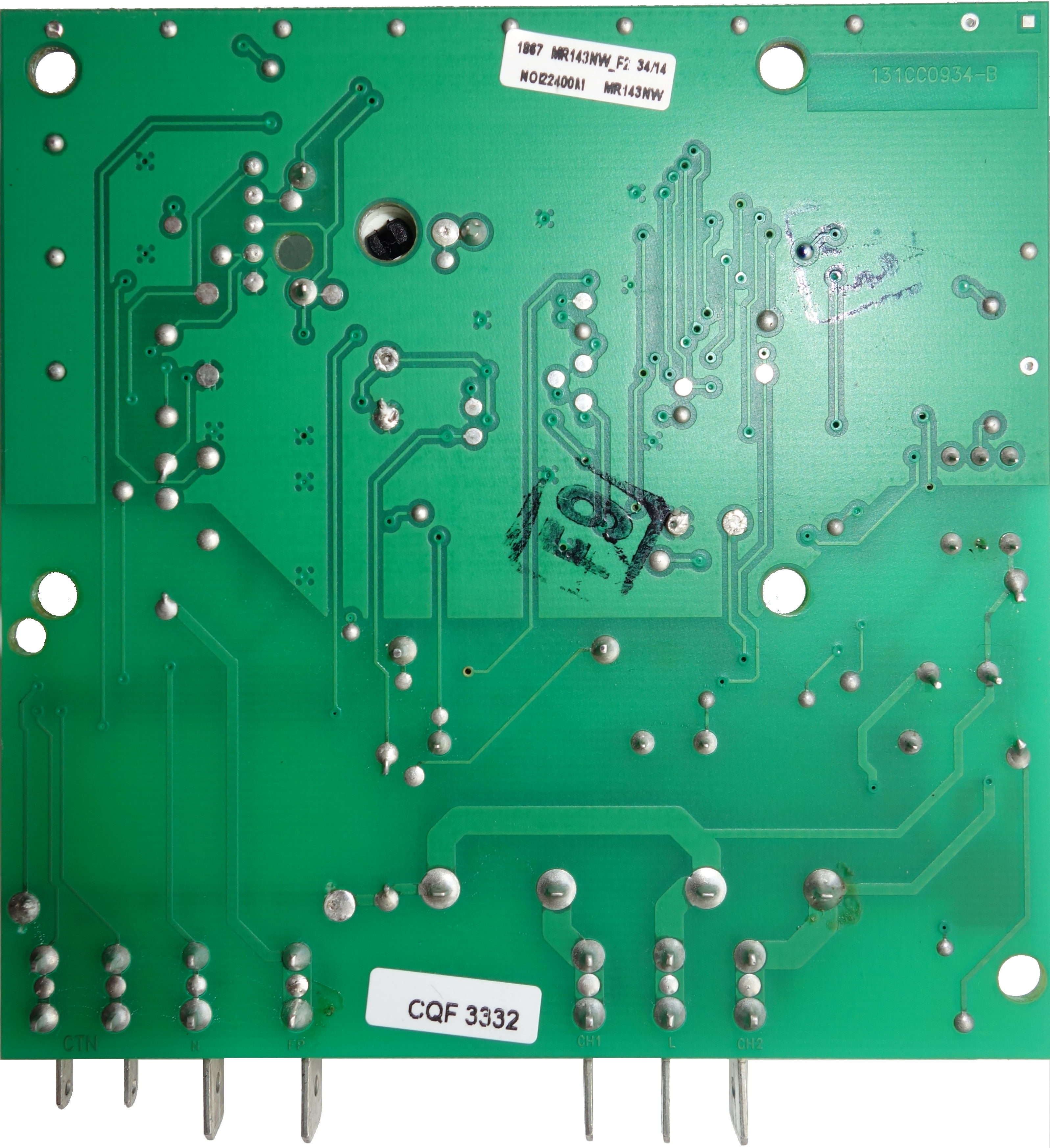
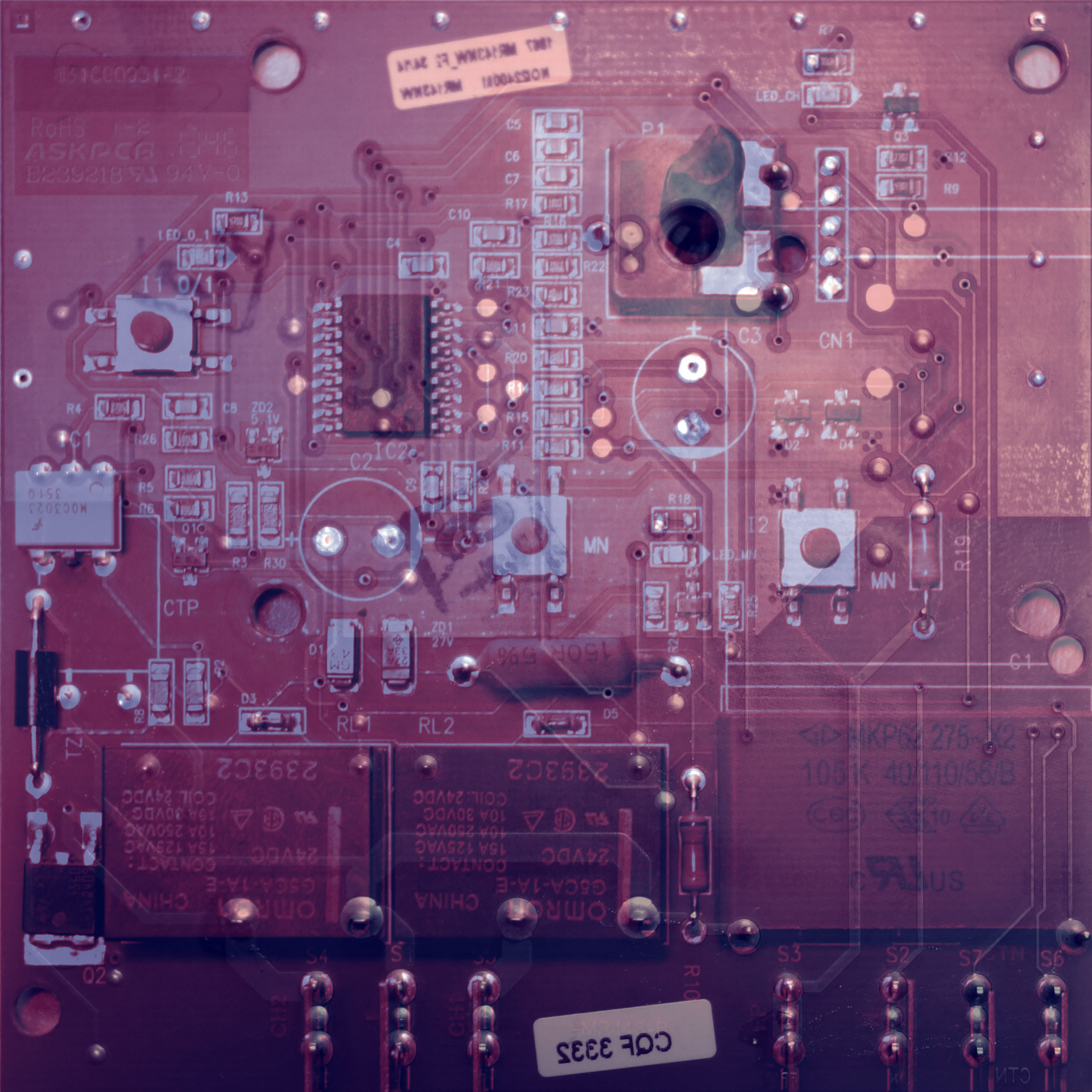
At first, the controller board looks very simple.
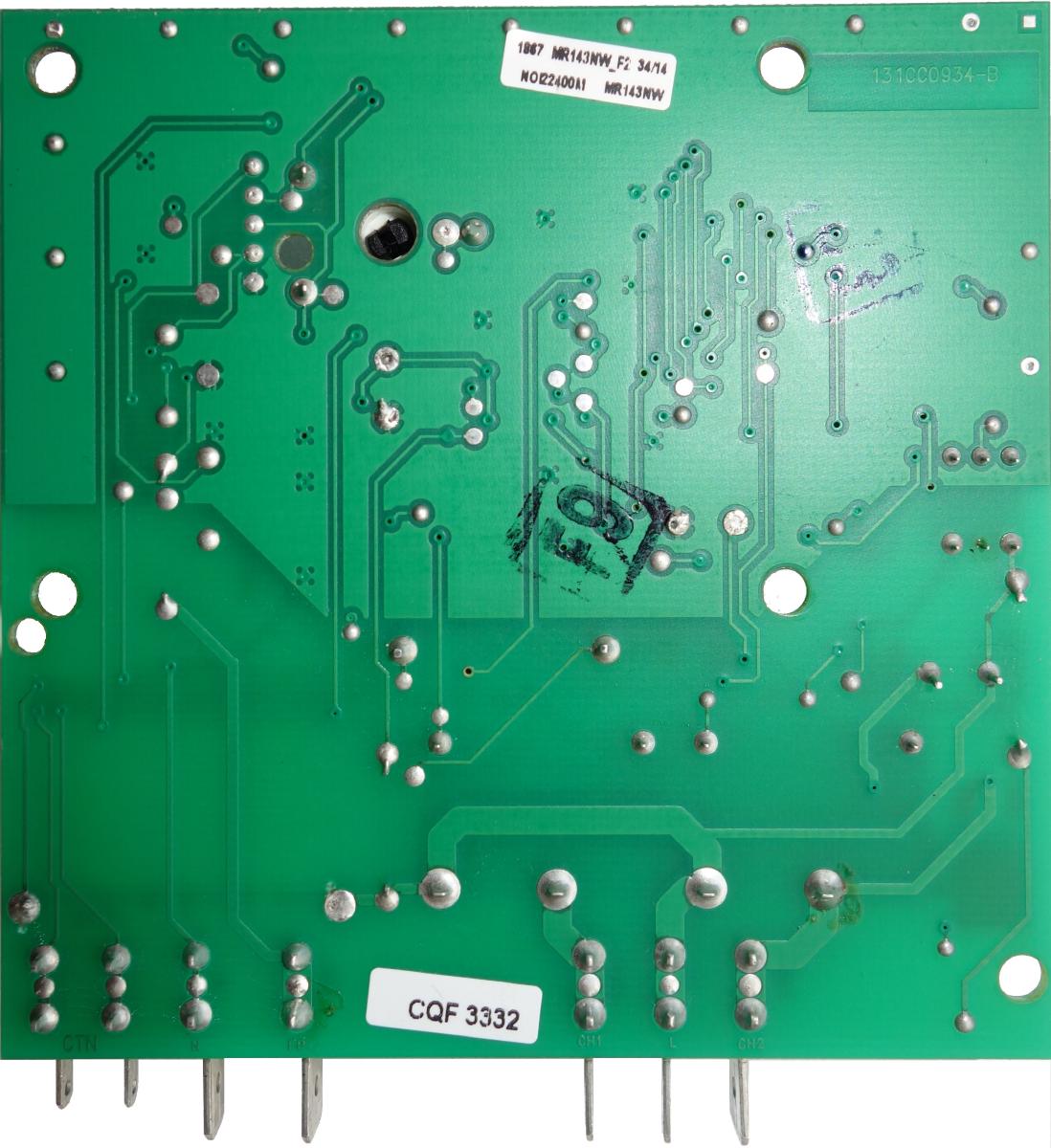
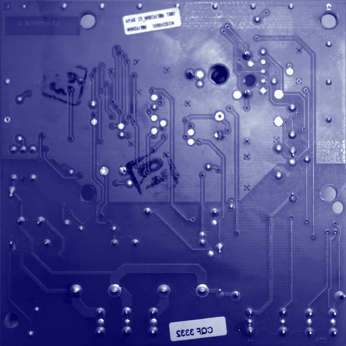
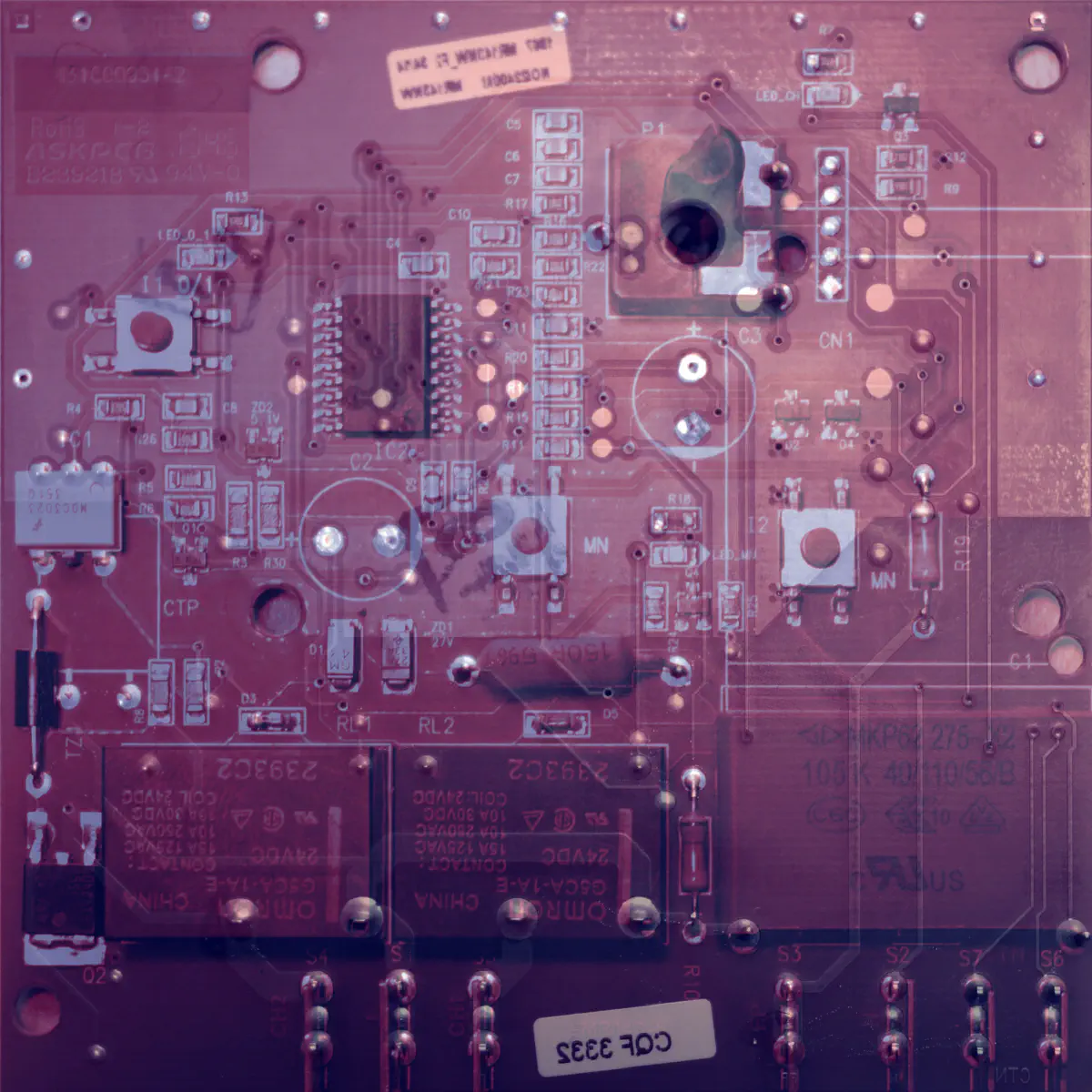
By exposing the board to a strong light and looking through it, there are only two copper layers.
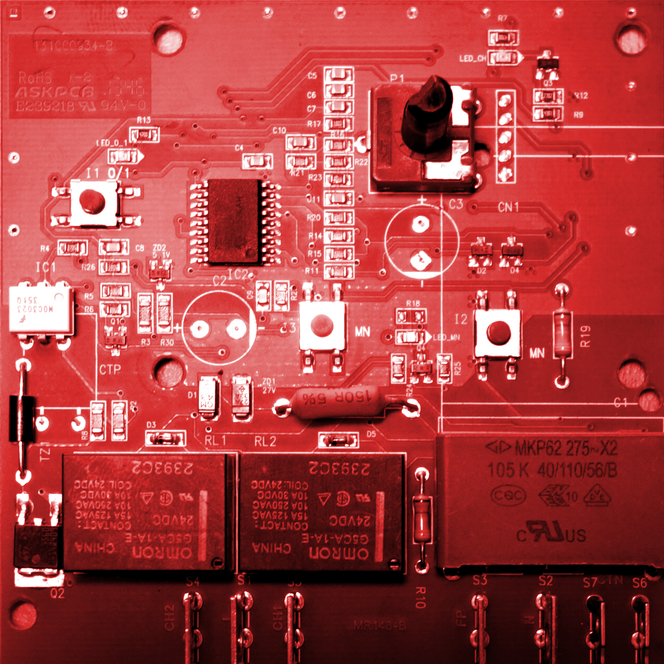
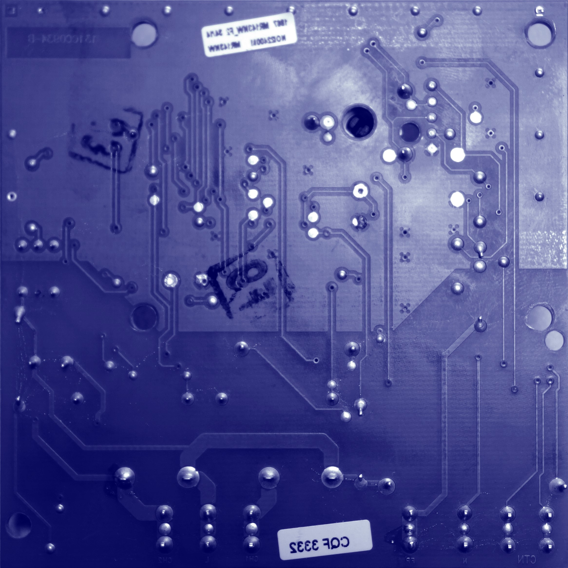
I will be able to reverse engineer the schematic. My method is simple, I take a picture of the top side, then another of the bottom side. Then I apply a red color filter for the top side and a blue color filter to the bottom side. My target is to get something as close as on a layout software.

Original files :
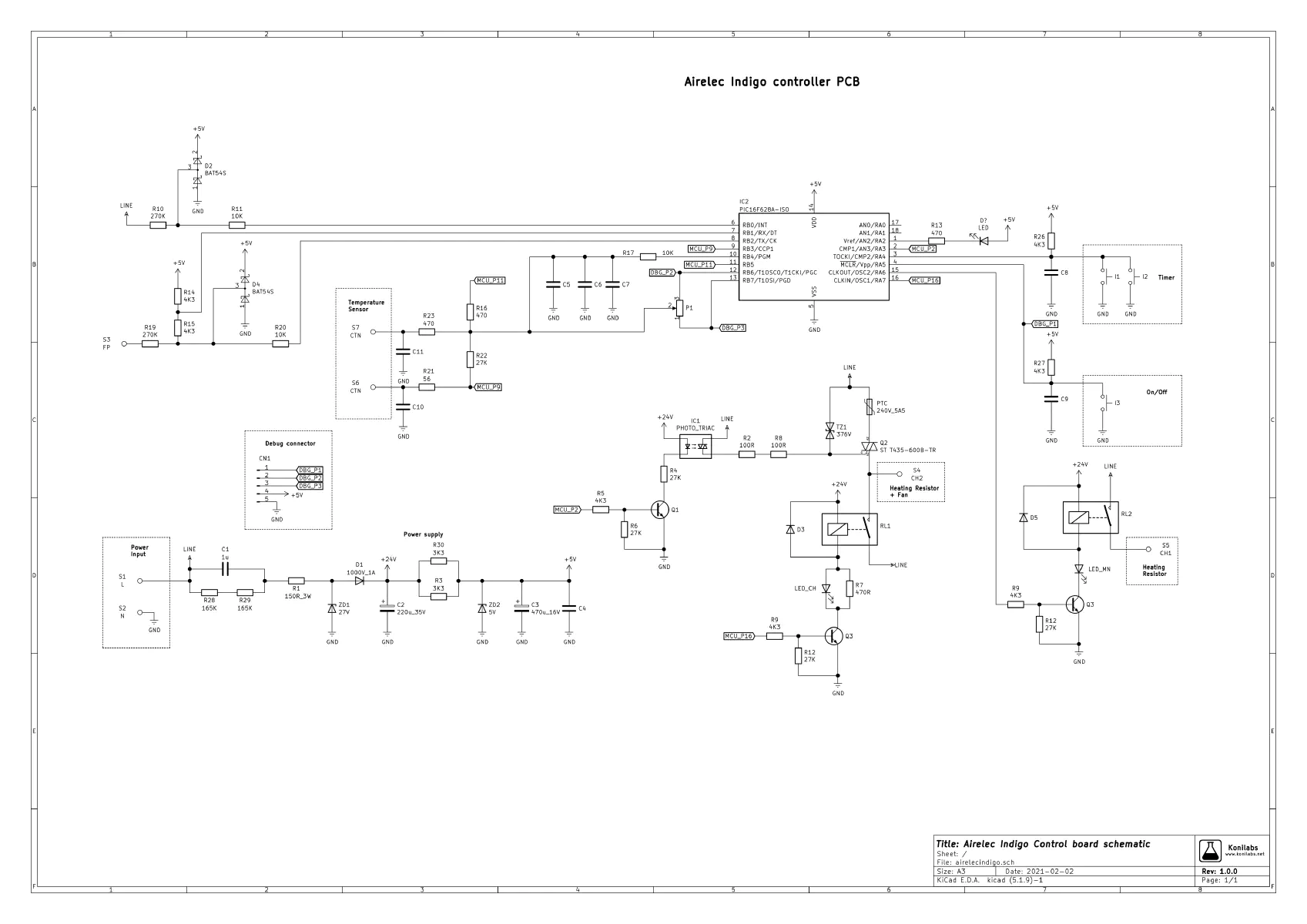
With a bit of patience, we finally get this schematic by following copper tracks :

I did not bother to measure each small ceramic capacitors, because I would have to unsolder them one by one to measure them out of the circuit.
Original files :
How the schematic works
I will explain here how main parts of the schematic are working. PCB design is really cost optimized with some clever tips.
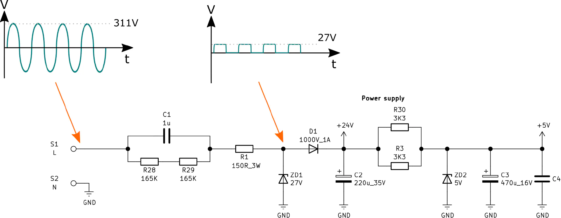
Power supply

Power supply part is designed to be cost efficient. It is a half-bridge rectifier with a Zener diode for 24 V voltage regulation (relay power supply) and another Zener diode for 5 V (microcontroller supply).
C1 and R1 are limiting the current flowing inside ZD1 Zener diode.
C1 behaves like a fixed resistor at 50 Hz. One microfarad capacitor value at 50 Hz frequency is equivalent to a 3.2 kOhm resistor.
$$ Z_{C_1}=\frac {1} {2 \times \pi \times f \times C_1}=\frac {1} {2 \times 3.14 \times 50 \times 1.10^{-6}} = 3185 \Omega $$
R28 and R29 will discharge C1 when the mains voltage is disconnected. This is a safety mechanism to prevent electric shocks because C1 can stay charged with mains voltage.
ZD1 is a Zener diode, it cuts negative voltage parts and reduces positive part of the sinus to 27 V.
D1 prevents current leakage from C2 back to the main voltage.
At C2 terminals, we have a regulated 24 V DC.
5V power supply is generated by ZD2 Zener diode. Current flowing through it is limited by R30 and R3. C3 smoothing capacitor allows to obtain a stable 5 V DC.
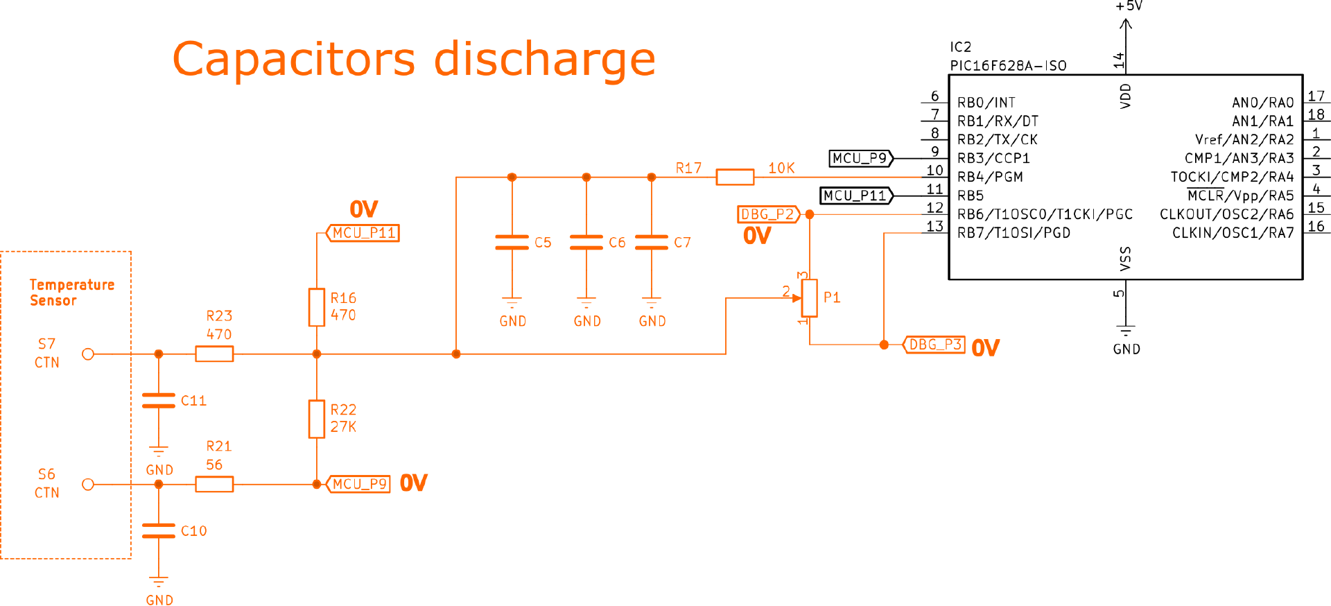
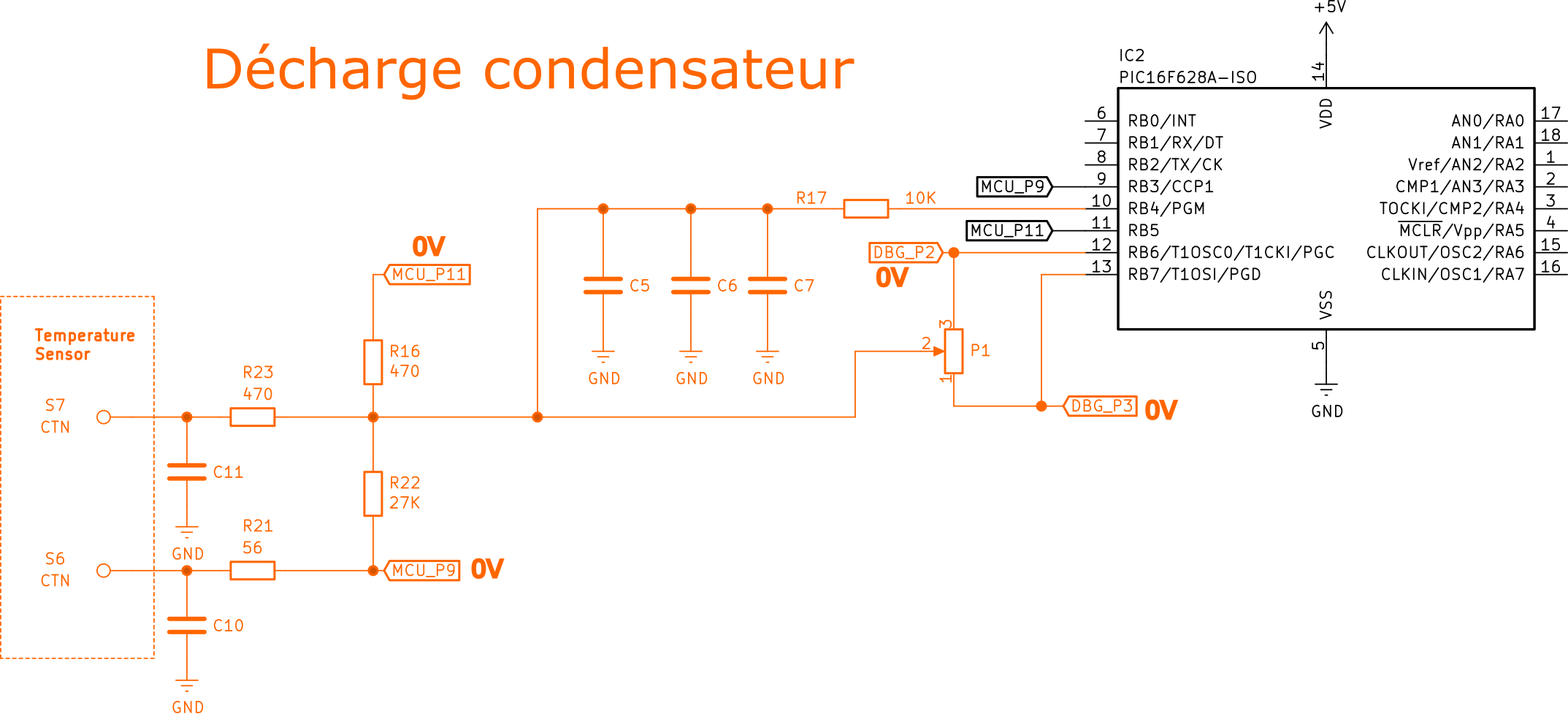
Temperature and potentiometer measurement
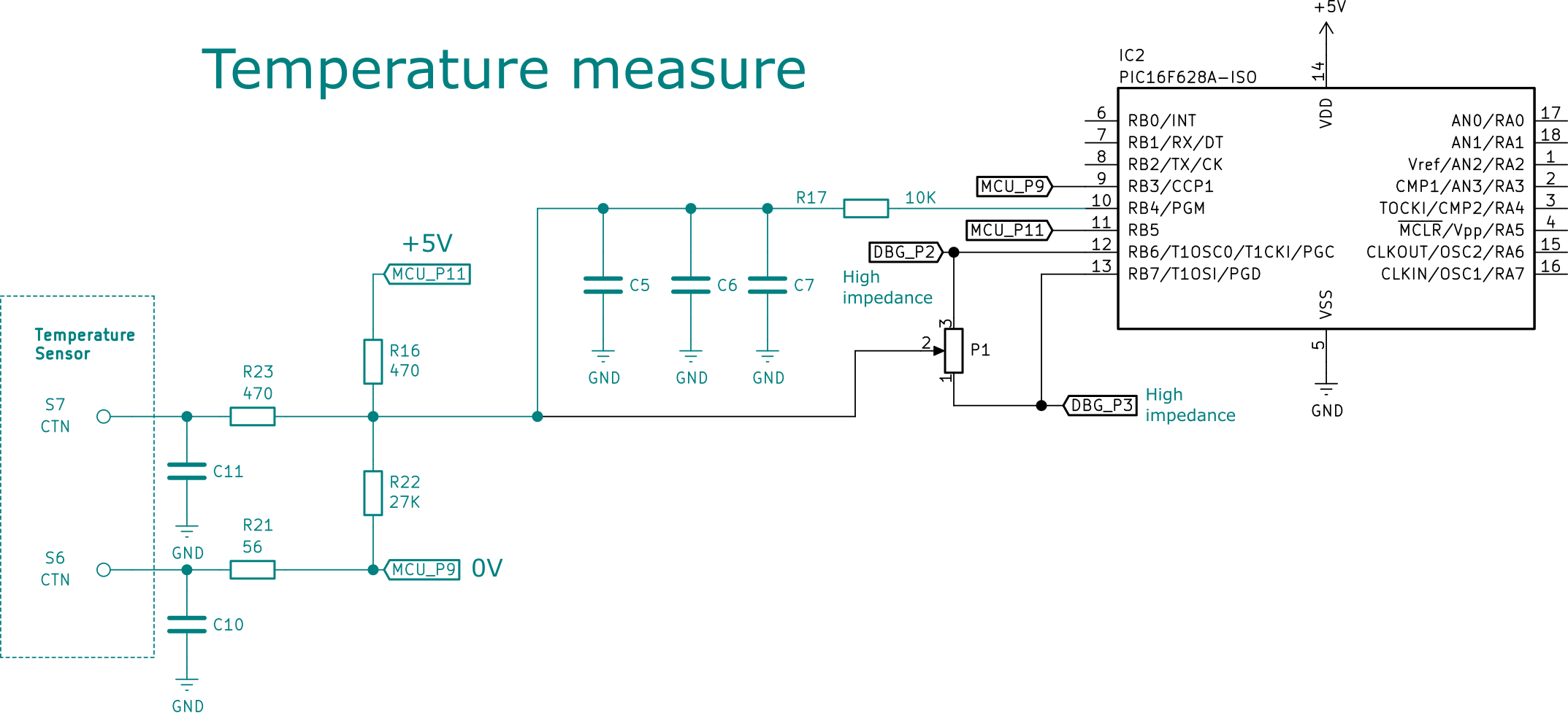
It is the cleverest part of the schematic. Microchip PIC16F628A microcontroller used here does not have an analog-to-digital converter (ADC).
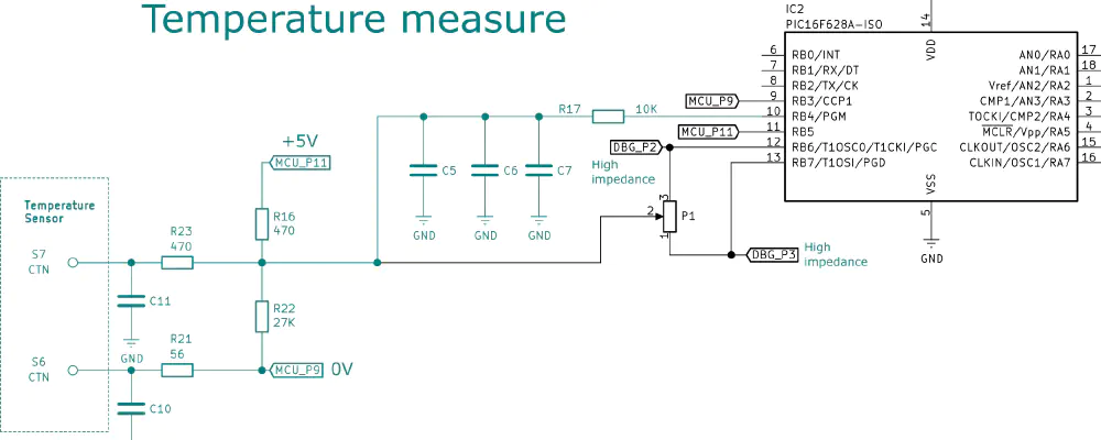
The position of the potentiometer and the room temperature coming from the sensor will be measured using digital input threshold of IC2 RB4 pin.
The NTC temperature sensor ic connected to S7 and S6 pins. It is a resistor whose value changes according to the temperature.
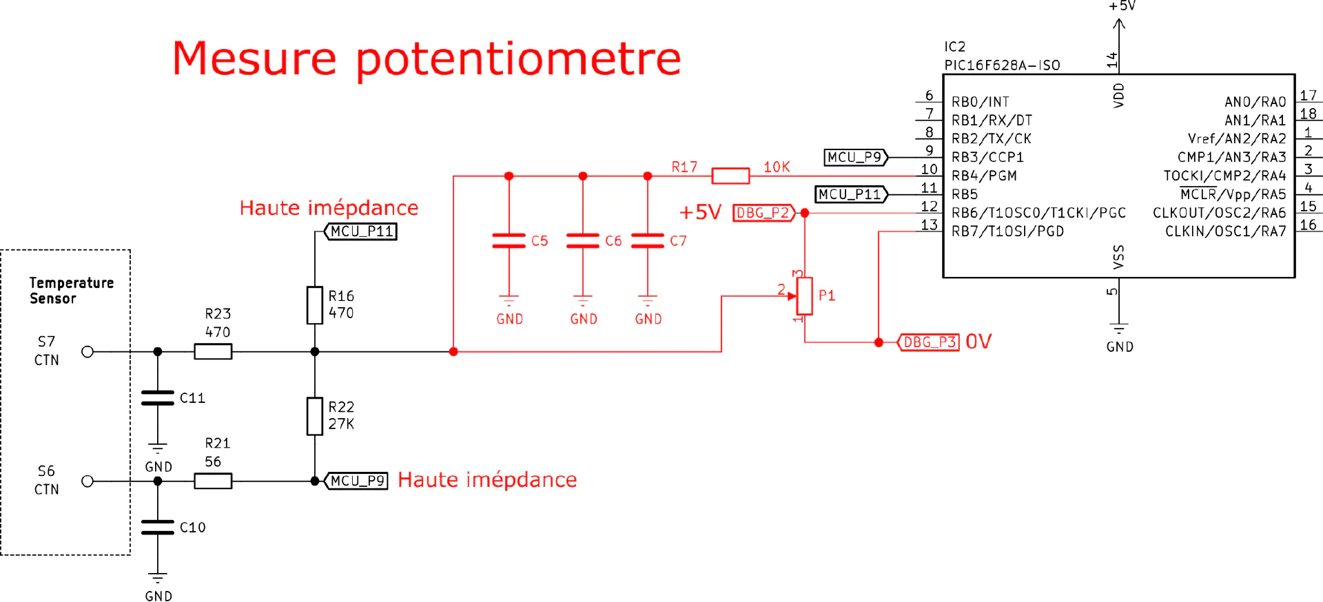
To start the measure of the temperature, microcontroller firmware changes RB6 and RB7 pin states to high impedance. This disconnects the potentiometer part. RB5 pin is set to high-voltage state (5 V), RB3 is set to low-voltage state (Ground). The microcontroller counts the time until RB4 pin toggles from low state to high state. This time duration allows to determine the temperature.
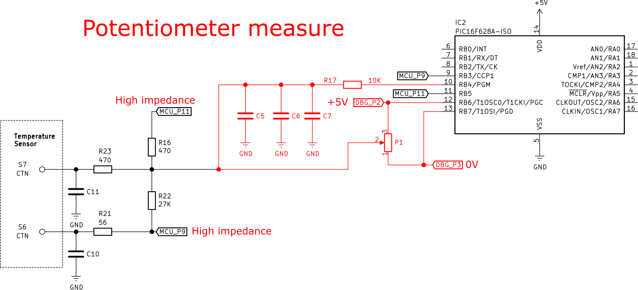
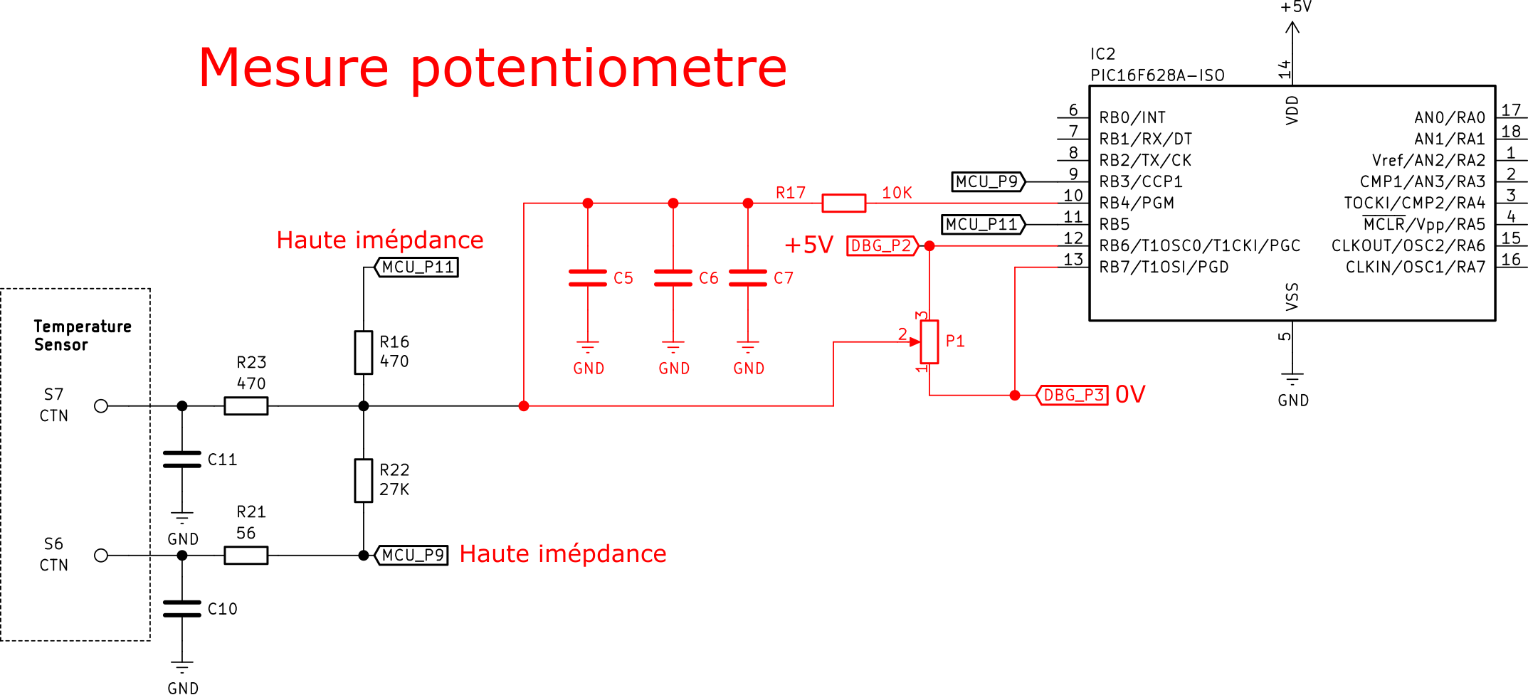
To get the position of the potentiometer. The microcontroller firmware set RB3 and RB5 to high impedance state. This isolate the temperature sensor part. RB6 is set to high-voltage state, RB7 is set to low-voltage state. Then, the microcontroller counts the time until RB4 pin toggles from low-voltage state to high-voltage state. Potentiometer position can be determined from the measured duration.
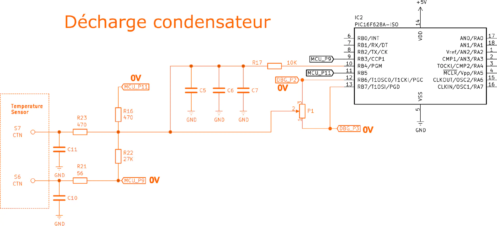
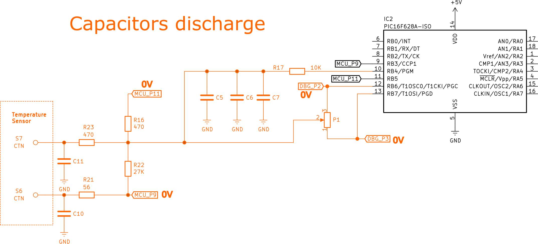
Between two measurements, RB3, RB4, RB5, RB6 and RB7 are set to low-voltage state to discharge C5, C6 and C7 capacitors.
This cycles repeats forever : capacitor discharge, potentiometer measure, capacitor discharge, temperature measure.
Here is a summary table :
| Mode | RB3 | RB4 | RB5 | RB6 | RB7 |
|---|---|---|---|---|---|
| Potentiometer measurement | Hi-Z | Hi-Z | Hi-Z | 1 | 0 |
| Temperature measurement | 0 | Hi-Z | 1 | Hi-Z | Hi-Z |
| Discharge | 0 | 0 | 0 | 0 | 0 |
Hi-Z = High impedance or input
0 = Low-voltage state 0 V
1 = High-voltage state 5 V
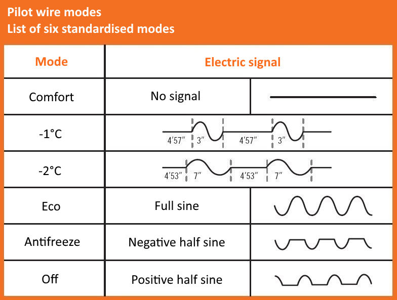
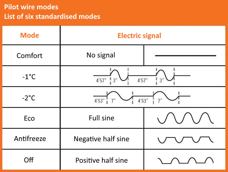
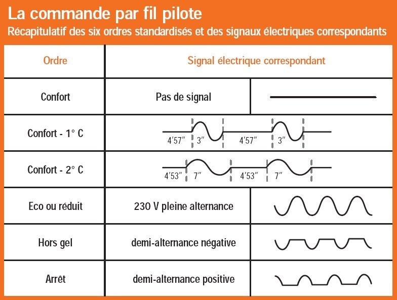
Pilot wire detection
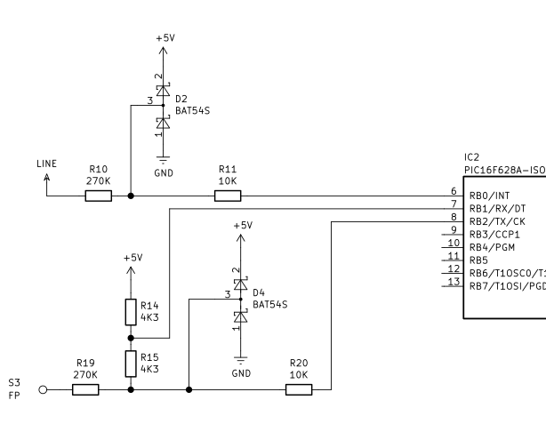
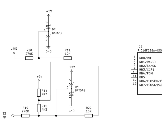
The pilot wire is a wire that allows to control a heater from a central controller. There are six different standardized modes (comfort, comfort -1 °C, comfort -2 °C, Eco, antifreeze and off) according to the wire signal. Main voltage sine signal is modulated. To detect the correct mode, we need only to detect if wire voltage is positive, zero or negative. Mains signal frequency is 50 Hz, microcontroller frequency is much higher with several MHz. Simple method consists of sampling the value of the pilot wire at regular intervals.
Schematic is very simple. D4 double diode protects the microcontroller by cutting voltage higher than 5 V and lower than 0 V.
When pilot wire voltage is positive, D4 clips the voltage at 5 V, RB1 and RB2 pins are in the high-voltage state.
When pilot wire voltage is zero, RB1 voltage level is 0 V. On RB2 pin, there is a voltage divider with a ratio of 0.5 created by R14 and R15. RB2 voltage is 2.5 V, according to microcontroller specification, high-voltage threshold is 2.0 V, RB2 is therefore in the high-voltage state.
When pilot wire voltage is negative, RB1 pin voltage is at low state, RB1 and RB2 pins are at 0 state.
| Pilot wire voltage | RB1 | RB2 |
|---|---|---|
| Positive | 1 | 1 |
| Zero | 1 | 0 |
| Negative | 0 | 0 |
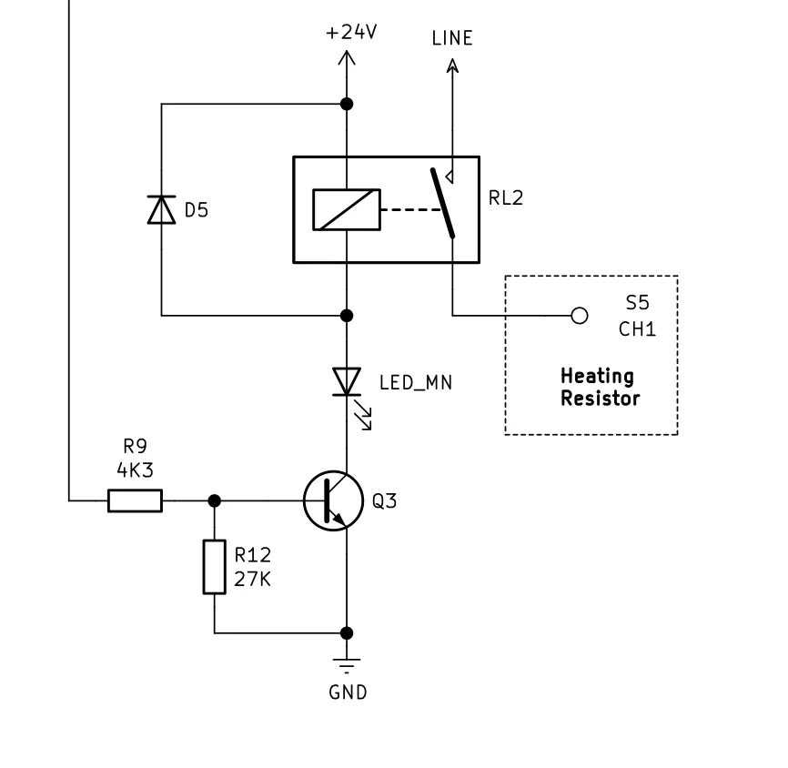
Heating element control

This is a very classic relay circuit. When RA6 pin is in high-voltage state, Q3 transistor conducts, current is flowing inside RL2 coil. It closes the contact. D5 is a freewheeling diode. It is used to absorb the coil overvoltage when Q3 no longer conducts.
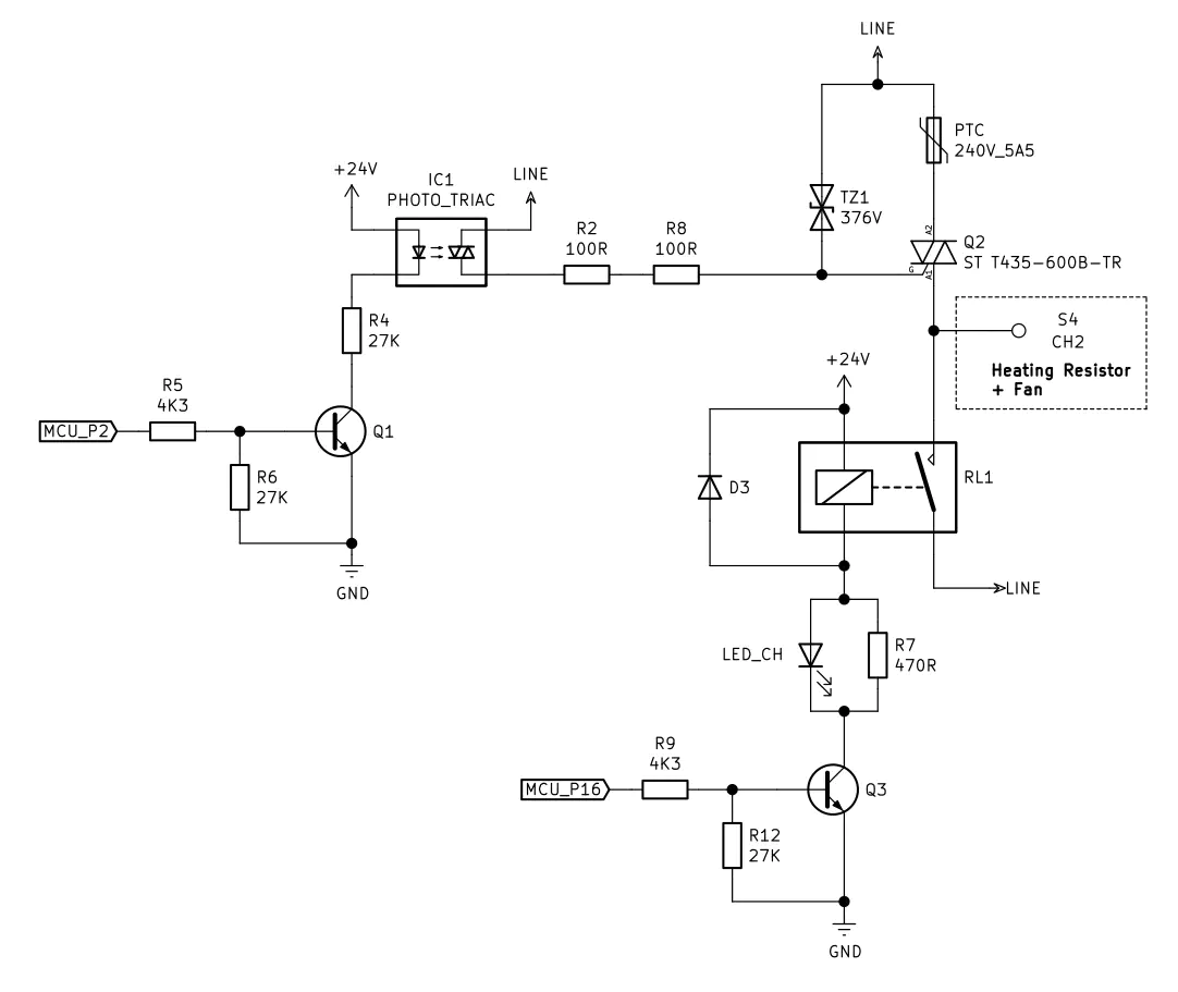
Heating element and fan control

This is exactly the same circuit as before with an additional Q2 Triac. This circuit controls the fan which is an inductive load. Using a simple relay is not the right solution, there will be electric arcs during relay switching. Relay lifetime will be much shorter. On the other hand, the Triac will withstand the peak current well during switching, but its static on state resistance will produce too much heat.
This circuit uses hybrid switching to get the best of static and mechanic switching. The Triac is switched first to absorb the current peak, then relay mechanical contact is switched. When switching off the fan, RL1 mechanical contact opens first then Q2 opens.
Repair and diagnostic
Failure happens when the fans start. After few seconds, the towel dryer stops and restarts. This kind of issue is clearly a power supply problem. My first idea is to verify chemical capacitors health. To do so, I will use a component test which allows to verify capacitor value and to measure the equivalent series resistor value. It often happens that the value of the capacitor is valid, but equivalent series resistor is too high. This limits the ability of the capacitor to absorb and deliver high currents.
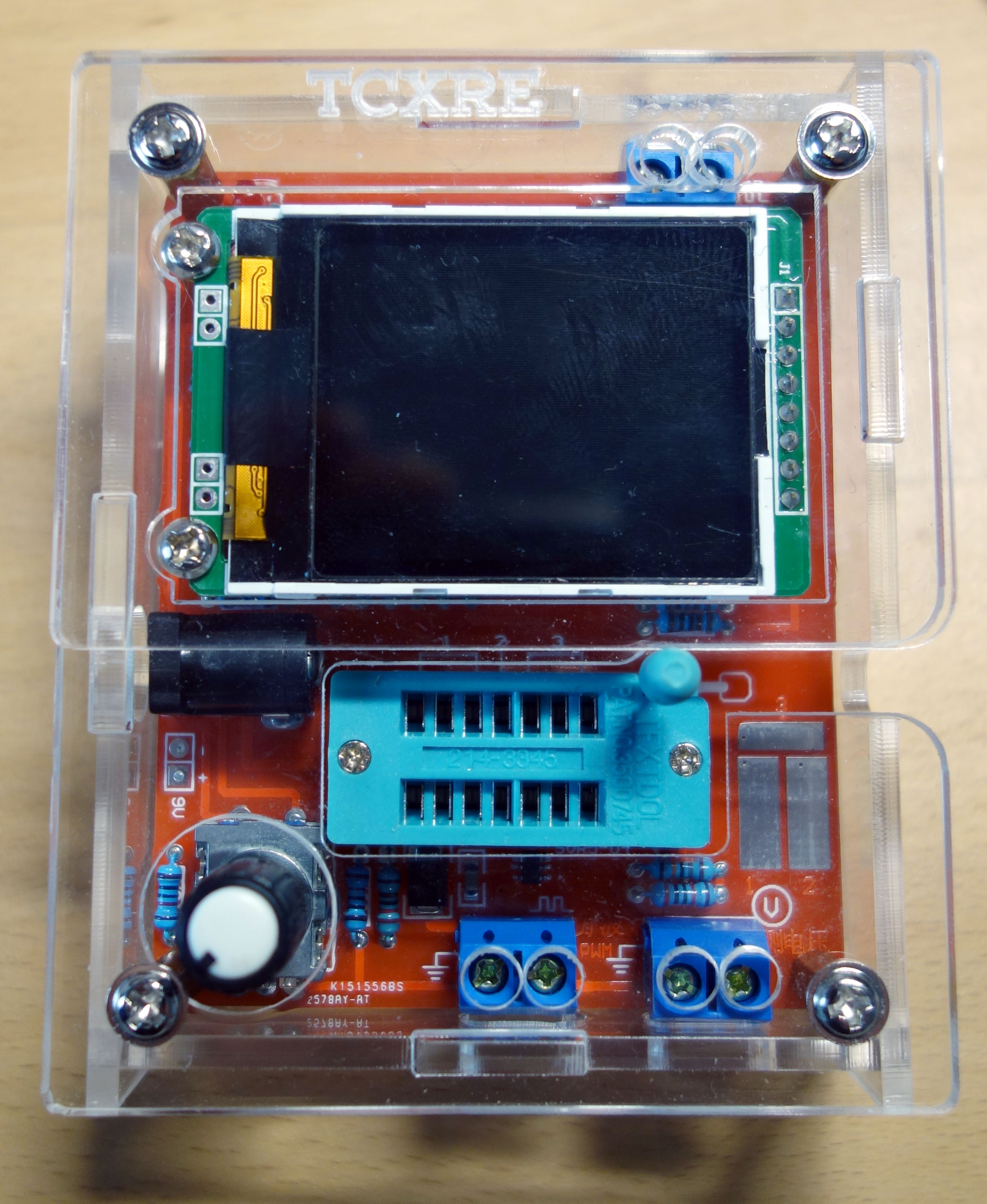
I use an ATMega328 based component tester which can be easily found on [eBay] (https://www.ebay.fr/sch/i.html?_from=R40&_trksid=p2380057.m570.l1313&_nkw=atmega328+component+tester&_sacat=0) for about ten euros. I like this tool, it allows to quickly test resistors, transistors and capacitors.
C2 and C3 electrolytic capacitors test gives nothing. Both are working perfectly.
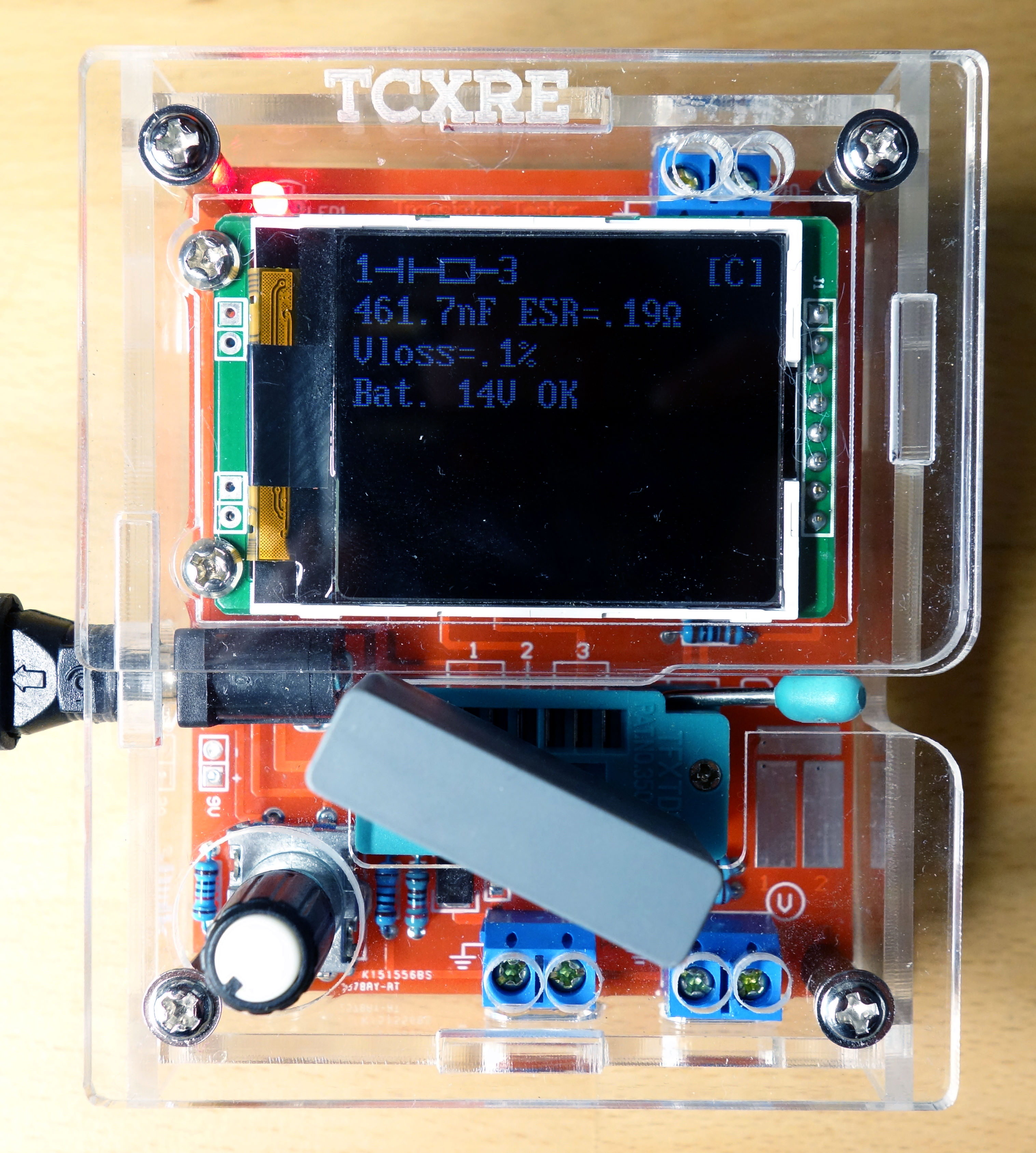
I decide to test C1 input power supply capacitor. This is a 1 µF polypropylene X2 class capacitor. Measured value is 461.7 nF. I finally found the failing component, its impedance under 50Hz frequency should be \( 3185 \Omega \), in reality it is \( 6893 \Omega \), this is twice as expected! This limits a lot the current that can be supplied by the power supply part. When switching on RL1 coil, consumed current goes high. Power supply voltage goes down which results in a microcontroller reset loop.
- My friend eBay allowed me to find a new capacitor for 3 euros shipped. After replacement everything works again 😍 .
-
warning: Warning, when replacing capacitors that are connected to the mains, be careful to choose class X2 references to avoid any risk ⚠️
Conclusion
At the end, I managed to repair the towel dryer easily. I was really happy to learn how this device works. I find it generally well built, it is a pity that a simple capacitor broke it down. My father having a second identical model, I hope that this problem is only a “bad luck” failure. For me, repairing household appliances is a good school of electronics. It is easy to find documentation and schematic on internet. On the other hand, it usually touches 220 V … so be careful! I hope that my explanations were clear! See you soon!


